Interrupteur Télémétrique Programmable à Ultrasons
Si on s'approche, ça s'enclenche ....
Quoi ? qu'est ce qui s'enclenche ? Eh bien,... ce que l'on veut !
Suivant ce que l'on va relier au bout, on pourra allumer une vitrine si des curieux s'approchent; On pourra arrêter ou mettre en route une pompe si le niveau d'eau ou de liquide monte, ou s'il est trop bas; avertir si une personne ou un animal s'approche au delà de la distance réglée; Et en mode buzzer, détecter si un véhicule nous approche par l'arrière alors que l'on est en vélo; voir même nous indiquer si on est encore loin du mur en rentrant la voiture au garage. Entre l'imagination et le besoin, il n'y a pas de limite ...
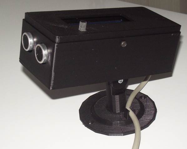
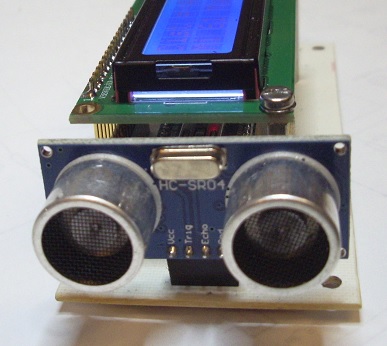
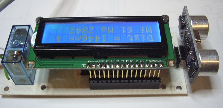
Nous avons une boite à fixation murale, ou libre de modifications, qui inclue un transmetteur à ultrasons, un afficheur et un bouton pour assurer l'interfaçage homme/machine . A la mise sous tension, le LCD s'allume et affiche les éléments suivants:
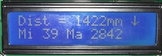
- La distance mesurée instantanée en mm
- La tendance au rapprochement ou à l'éloignement par une flèche, dont le sens indiqué, dépend du sens du mobile ! Pendant la marche normale, un rapprochement rallumera le rétro éclairage de l'afficheur .
- On aura également la plus petite valeur enregistrée depuis la mise sous tension .
- On aura également la plus grande valeur enregistrée depuis la mise sous tension .
- Une coupure de l'alimentation effacera ces deux valeurs
- Dans un souci d'économie, si l'alimentation est sur batterie, le rétro-éclairage s'éteint au bout de 20" et se rallume si le mobile s'approche.
Pour régler la distance d'activation de la sortie (sur relais ou buzzer), un appui long sur le bouton nous renverra vers ce menu, et le maintien enfoncé incrémente cette distance ! puis un relachement long et une nouvelle action sur le bouton ajustera la durée de l'état 'activé' suivant ce que l'on veut commander .
Attention, sans sauvegarde de la tension d'alimentation, les données et réglages seront perdus, en cas de coupure .
La sortie pourra se faire sur relais ou sur buzzer ! La sérigraphie du circuit accepte les deux versions; si l'on souhaite simplement être avisé d'une distance minimum ( vélo, mur du garage, approche d'une personne) on câblera l'option buzzer ou sirène. Dans les cas où l'on souhaite commander un appareil, on montera l'option relais, qui nous laissera l'entière liberté du choix de l'élément à piloter. .
Le boîtier et l'étrier de fixation sont réalisés à l'imprimante 3D et pourront être adaptés aux besoins de chacun .
Bon, voyons comment ça marche ....
Pour faire de la télémétrie par ultrasons, il suffit de générer un signal de 36 à 44 Khz en direction d'un obstacle et d'en attendre un retour d'écho; Sachant que le son se promène à 340 mètres par seconde dans l'air (sous condition de température et de pression ), il sera facile de mesurer le temps entre l'émission du signal et la réception de l'écho, et de le diviser par deux (aller et retour) pour calculer la distance ....Un processeur avec ALU va se friser les moustaches pour faire ces calculs !
Le schéma:
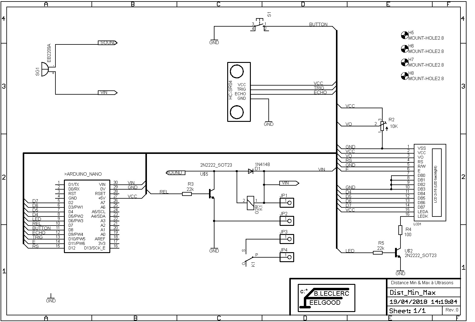
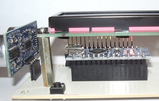
L'électronique est des plus simple, grâce à l'utilisation d'un Arduino Nano à 2€ qui va assurer toutes les fonctions. On ne s'embête pas à créer le module à ultrasons ; Un HC-SR04 , à 0,80€ , va combiner l'émission et la réception... Une mise au potentiel haut de la borne trigger de 10µs va envoyer une salve d'ultrasons et enclencher la mesure de temps jusqu'à ce que la pin Echo avoue la réception d'un signal ! Celui-ci va être traité par l'ALU et envoyé à l'afficheur . C'est un modèle standart 2 lignes, 16 caractères, piloté par deux mots de quatre bits sur les broches des entrées de poids le plus fort (D4 à D7). La validation est assurée par la pin 'enable' quand le demi mot est présent et la commutation R/S informe l'électronique du circuit d'affichage, s'il s'agit de données d'instructions ou de caractères . Pas d'affolement, tout se fait très bien par l'appel d'un sous-programme dédié à cet effet (on ne va pas passer sa vie à refaire le monde). Le contraste des caractères est réglé par le potentiomètre ajustable de 10K. Le rétro-éclairage est piloté par la sortie PWM (D6) qui, via la résistance de base de 22K du transistor CMS 2N2222, va commander l'allumage à travers la résistance de limitation R4. L'éclairage est en principe coupé en marche normale après une poignée de secondes et ne s'allume seulement si la distance diminue ( approche du HC-SR04).
Le relais est excité par la sortie REL (D7), via un transistor 2N2222 CMS, dont l'intensité dans la base est limitée par la 22K. (R3). Une diode de roue libre, absorbera les inductions transitoires générées par la rupture du courant sur la bobine . La sérigraphie du circuit permet de remplacer le relais par un buzzer ou une sirène suivant l'adaptation que l'on aura choisi. Que la sortie soit de n'importe quel type, l'activation de celle-ci se fera lorsque la distance pré-réglée est inférieure ! Et elle restera activée le temps qui à été défini lors du réglage ...
Le bouton de réglage vient tirer à la masse le potentiel de l'entrée D8... Une résistance de pull up a été déclarée dans le programme afin de s'affranchir d'un élément matériel qui, en plus du coût, aurait chargé la réalisation . Puisque le Nano le permet, pourquoi s'en priver ? Après mise sous tension un appuis de 3" sur bouton vas afficher une distance en millimètres, qui va s'incrémenter tant que l'on maintiendra le bouton; cette valeur correspondra à la distance qui enclenchera la sortie . Après le relâchement, un nouvel appui fera la même chose pour définir le temps pendant lequel durera cette activation ... Tant que le courant ne sera pas coupé, ces grandeurs resteront mémorisées ad vitam eternam. Tout ceci pour dire qu'il faudra penser à secourir l'alimentation si l'on veut ne pas avoir à reprogrammer la distance et le temps régulièrement .
Le Circuit Imprimé:
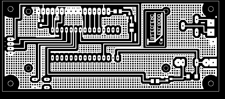
Le circuit imprimé est de type simple face, routé sous Eagle, avec une priorité pour les composants CMS plutôt que traversants. La sérigraphie permet de câbler un relais, un buzzer ou une sirène suivant l'option choisie sans modification du traçage . Tout les fichiers nécessaires se retrouvent dans le Zip plus bas .
Le Sketch et le Boîtier :
Le programme ou sketch est déroulé en mode texte ci-dessous, et en fichier .ino dans le zip avec les fichiers de réalisation.
Je ne vais pas m'étendre sur les commentaires, car le détail est donné en bout de chaque ligne pour en comprendre ce que j'ai voulu faire.
Le gros avantage, c'est que chacun peut personnaliser son sketch au gré de ses besoins et de ses idées .
/* Ultrasonic Switch Relay activ up by the distance and the time preseted.
* by Bernard LECLERC 08/2018
*/
#include <LiquidCrystal.h> // include library code
#define TRIGG 10 // Output TRIGGER
#define ECHO 9 // Input Return ECHO
#define BUTTON 8 // Input Button
#define REL 7 // Output Relais
#define LED 6 // Command Back light
int tempo; // value loop relay activ
int numlight; // Value loop backlight
const long TIMEOUT = 25000UL; // 25ms = ~8m à 340m/s
float son= 340.0 / 1000; //sound's speed (mm/µs)
float Dmin, Dmax, Dprevious, DSetAl, SetTime; // Other data values
byte trend = ' '; //trend of distance measurements, up or down
const int rs = 12, en = 11, d4 = 5, d5 = 4, d6 = 3, d7 = 2; // LCD Pin's connection
LiquidCrystal lcd(rs, en, d4, d5, d6, d7); // initialize the library by associating any needed LCD interface pin
byte up[8] = { //defines upward arrow character
B00100,
B01110,
B10101,
B00100,
B00100,
B00100,
B00100,
};
byte down[8] = { //defines downward arrow character
B00100,
B00100,
B00100,
B00100,
B10101,
B01110,
B00100,
};
void setup()
{
lcd.createChar(0, up); //creates custom character (gylph) number 0 following definition "byte up[8]"
lcd.createChar(1, down); //creates custom character (gylph) number 1 following definition "byte down[8]"
lcd.begin(16, 2); // set up the LCD's number of columns and rows:
pinMode(TRIGG, OUTPUT); //Set the pin as Output
digitalWrite(TRIGG, LOW); // Set the TRIGGER pin to LOW stat..
pinMode(ECHO, INPUT); //Set the pin as Input
pinMode(BUTTON, INPUT_PULLUP); //Set a pull up résistor on the button
pinMode(REL, OUTPUT); //Set an Output Relay
digitalWrite(REL, LOW); // Set the Relay pin to LOW stat..
pinMode(LED, OUTPUT); //Set an output back light
digitalWrite(LED, HIGH); // Set the LED pin activ max..
}
void loop()
{
debut:
digitalWrite(TRIGG, HIGH); // Mesurement begin by send
delayMicroseconds(10); //a puls HIGH to 10µs on the pin TRIGGER
digitalWrite(TRIGG, LOW);
int mesure = pulseIn(ECHO, HIGH, TIMEOUT); // Time between send et receive the ultra-sound
float distance_mm = mesure / 2.0 * son; //calcul the distance by the time
if (distance_mm<Dmin)
{Dmin=distance_mm;}
if (distance_mm>Dmax)
{Dmax=distance_mm;}
if (distance_mm > (Dprevious + 50)) //distance is increasing
{trend = byte(1);
digitalWrite(LED, HIGH);
numlight = 0;
}
if (distance_mm < (Dprevious - 50)) //distance is decreasing
{trend = byte(0);
}
if (numlight > 15){digitalWrite(LED,LOW);} //Shutdown backlight after many loop
if (Dmin<1 )//Preset first time a minimal value
{Dmin = 3500; }
Dprevious = distance_mm; //remember current measurement
lcd.clear(); // Clean display and show the messages and values
lcd.print("Dist = ");
lcd.print(distance_mm,0);
lcd.print("mm ");
lcd.write(trend); // write upward or downward arrow
lcd.setCursor(0, 1);
lcd.print("Mi ");
lcd.print(Dmin, 0);
lcd.print(" Ma ");
lcd.print(Dmax, 0);
delay (1000);
if (distance_mm < DSetAl) { //Alarm didtance detected and jump sub-routine
goto alarme;
}
if (tempo > SetTime) { // Time to hold the relay on; Nb loop
tempo = 0; //reset the Nb of loop
digitalWrite(REL, LOW); //shut down the relay
}
if (digitalRead (BUTTON)==LOW) { //Jump to sub-routine "Set the baklight time"when the button is pressed
goto dist_set;
}
numlight = numlight + 1; //increase value for backlight time
tempo = tempo + 1; //increase value for relay time
goto debut;
dist_set:
digitalWrite(LED, HIGH);
DSetAl = DSetAl + 10;
lcd.clear();
lcd.print("Alarme = ");
lcd.print(DSetAl,0);
lcd.print("mm ");
delay (200);
if (digitalRead(BUTTON)==LOW) {// More and more since the button is pressed
goto dist_set;
}
delay (3000);
goto time_set; // and jump to the sub-routine "Set relay time"
time_set:
SetTime = SetTime + 1;
lcd.clear();
lcd.print("Tempo = ");
lcd.print(SetTime,0);
lcd.print("sec ");
delay (200);
if (digitalRead(BUTTON)==LOW) {// More and more since the button is pressed
goto time_set;
}
delay (5000);
digitalWrite(LED,LOW);
goto debut;
alarme:
digitalWrite(REL, HIGH);
digitalWrite(LED, HIGH);
goto debut;
}
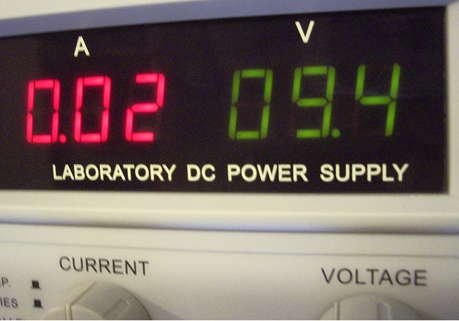
Dans un souci d'économie d'énergie, lorsque l'alimentation est assurée par des piles ou des batteries, le programme coupe le rétro-éclairage du LCD. celui-ci se ré-allume si la distance diminue ( un mobile s'approche ) ce qui donne une intensité de 20mA allumé et 10mA éteint . Une idée d'extinction progressive est tout-à-fait possible en utilisant la fonction PWM (modulation de largeur d'impulsion ) de la sortie utilisée par l'ajout d'une ou deux lignes de programme .
Le Boîtier :
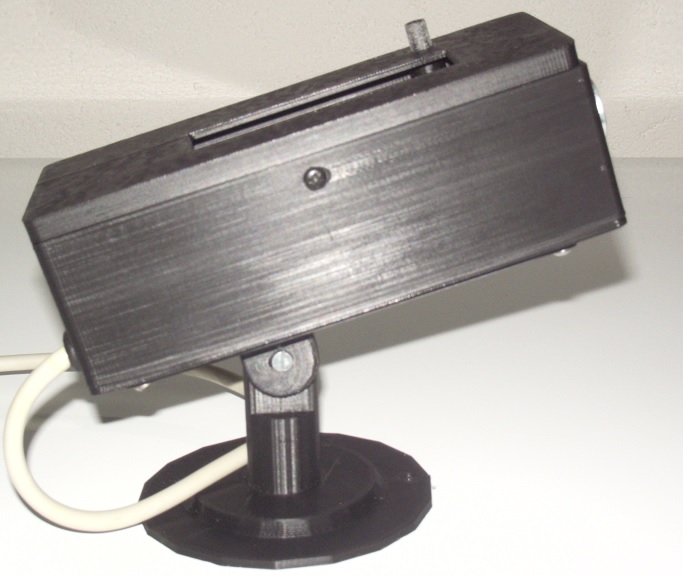
Le boitier est réalisé avec l'imprimante 3D, ajusté au circuit, en fil PLA et se compose de 6 pièces:
- Une rosace de fixation murale.
- Une chape mobile en rotation dans la rosace.
- Un support mobile, à basculement avec la chape, et fixé par les même vis que le circuit et la partie inférieure du boitier.
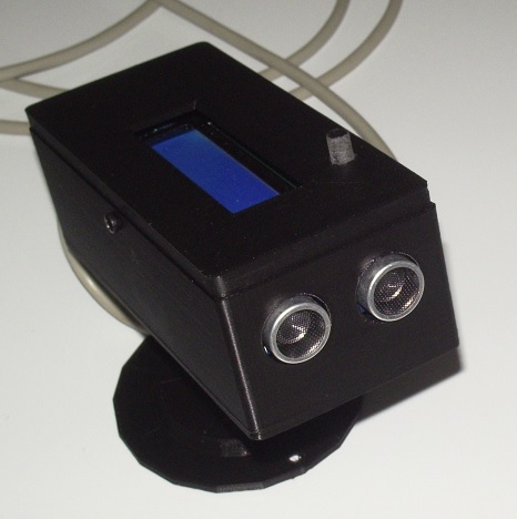
- La partie inférieure de la boite avec deux trous pour les transducteurs ultrasoniques .
- La partie supérieure avec une fenêtre de visualisation pour le LCD 2 lignes 16 caractères, les oreillettes de verouillage et le guide du bouton.
- Le bouton, avec sa plaquette d'appui sur le micro poussoir .
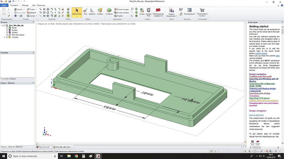
La création est faite par DesignSpark Méchanical et ensuite exportée en fichier .stl pour être traîté par le puissant pilote d'impression Repétier Host .
Et Ici, tout ce qui sert à la réalisation :
![]() Tlm (77.63 Ko)
Tlm (77.63 Ko)
Ajouter un commentaire